- Main Page
-
Products
- Goldwing Accessories
- AC Charging Station
- DC Charging station
- Garden Gate Motors
- Barriers
- Doors With Photocell
- Rising Bollards
- Road Blocker
- Security Barrier
- Circular Sliding Doors
- Traps
- Under Vehicle Scanning System
- Industrial Doors
- Turnstile Systems
- Parking Place Management System
- Plate Recognition System
- Vehicle Sensing Guidance System
- Loading Systems
- Automatic Passing Systems
- Accessories
- Electronic Cards
- CORPORATE
- Our Projects
- Authorized
- CONTACT
- SUPPORT
-
Documents
- Language
 Türkçe
 English
A properly designed system should restrict unauthorized entry, support pedestrian safety, operate reliably under the expected traffic volume, withstand environmental exposure and integrate with the site's access-control infrastructure. For this reason, selecting an automatic bollard should not be based solely on purchase price or appearance. Risk assessment, site survey, civil works, safety logic, installation and after-sales support must be considered as one system.
Bollard systems are used in a wide range of locations, including municipal squares, industrial facilities, public buildings, campuses, residential developments and commercial properties. However, not every bollard is designed for the same purpose. Some products are intended for routine traffic management and access control, while others may have independently verified impact performance for a defined vehicle mass, speed and installation configuration.
This guide explains what a bollard system is, how it works, the main product types, technical selection criteria, foundation and drainage requirements, maintenance planning, access-control integration and the questions that should be asked during procurement.
What Is a Bollard?
A bollard is a cylindrical barrier used to manage vehicle traffic, control access to a defined area or create a physical boundary between vehicles and protected spaces. Fixed bollards remain above ground at all times, while automatic rising bollards lower to road level when access is authorized and return to the raised position after the vehicle has passed.
Depending on the application, bollards may be hydraulic, electromechanical, manual, fixed or removable. Their functions generally fall into three categories:
- Managing and authorizing vehicle access,
- Creating a visible and physical boundary between pedestrian and vehicle zones,
- Providing a higher level of verified protection when a model has been tested for a defined impact scenario.
Do All Bollards Provide the Same Security Level?
No. A strong appearance does not prove that a product has been independently impact tested. Standard access-control bollards and impact-rated models must be evaluated as different product classes.
A standard automatic bollard may be suitable for daily access management at car parks, factories, residential sites, municipal service areas or controlled streets. An impact-rated product is assessed using a specified test vehicle, mass, impact speed, penetration distance and installation arrangement. Therefore, the expression “high security” is not sufficient on its own. The exact model, test standard, test vehicle, mass, speed, penetration result and rating code should be verified.
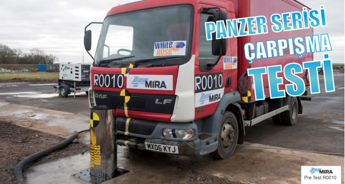
White Rose offers bollard models with American K12 and British IWA 14 crash test certifications for projects requiring a high level of security. These tests verify the physical security performance of barrier systems under defined vehicle weight, impact speed, and test conditions. When preparing technical specifications, the relevant test report, tested model, installation configuration, and compatibility with project requirements should be carefully evaluated.
 |
|
How Does an Automatic Rising Bollard Work?
The moving cylinder is raised or lowered by a control command. When an authorized access request is received, the control panel checks safety inputs and system status. If the conditions are safe, the bollard lowers and the traffic signal permits entry. After the vehicle leaves the protected detection zone, the bollard rises again.
A typical sequence is:
1. An access request is received through license plate recognition, RFID, a card reader, remote control, push button or security operator.
2. The control panel verifies safety sensors and operating status.
3. The bollard lowers and the traffic light indicates permission to proceed.
4. The vehicle is monitored by induction loops or other safety sensors.
5. Once the vehicle clears the safe zone, the bollard rises.
6. The system returns to standby for the next request.
The sequence can be adapted for emergency services, fire access, visitor management or higher-security entry procedures. At high-volume sites, queue length, lane capacity, interlocking and a secure holding area may also need to be designed.
Hydraulic Operating Principle
In a hydraulic system, an electric motor drives a pump that pressurizes hydraulic fluid. Valves control pressure and flow direction, and the cylinder converts hydraulic pressure into vertical motion. Depending on the design, the hydraulic power unit may be installed in a separate cabinet or integrated into a self-contained bollard.
Common advantages of hydraulic systems include:
• Power transmission suitable for frequent operation,
• Controlled and stable movement,
• The ability to operate several bollards from one power unit,
• Compatibility with accumulators and emergency operating modes,
• Long service life when maintained correctly.
Hydraulic hoses, fittings, seals, valves, fluid level and temperature conditions should be inspected periodically. No mechanical or hydraulic system should be described as completely maintenance-free.
Main Components of a Bollard System
Moving Cylinder
The visible cylinder that rises from the road. Diameter, height, wall thickness, structural steel, external sleeve and surface finish vary by model. A polished stainless-steel surface does not by itself indicate structural strength; the internal load-bearing construction must also be considered.
Underground Housing and Guidance System
This structure supports the moving assembly and guides vertical movement. Water, mud, sand and debris can affect performance, so cleaning access and drainage are essential.
Hydraulic Power Unit or Drive Mechanism
The drive system may include a motor, pump, reservoir, valves and hydraulic connections. In a self-contained design, these components are integrated into the unit; in a central system, they are installed in a separate cabinet.
Electronic Control Panel
The panel manages operating commands, safety inputs, traffic lights and access-control connections. Proper ventilation, surge protection, grounding, cable identification and service access improve reliability.
Safety Equipment
Induction loops, photoelectric sensors, traffic lights, acoustic warnings, LED indicators and emergency-stop devices connect the movement of the bollard to a safe operating sequence.
Access Authorization Equipment
License plate recognition, RFID readers, card systems, tag-based access, remote controls, intercoms, mobile applications and operator panels may be used. The authorization system and the physical barrier should be designed as a single operating scenario.
Types of Bollard Systems
Automatic Hydraulic Bollard
Suitable for frequent and controlled vehicle access. It can be integrated with access-control systems and operated individually or in groups. Municipal sites, factories, public buildings, campuses, business centers and residential developments are common applications.
Self-Contained Automatic Bollard
The power and control components are integrated into the product. This can be advantageous where cabinet space is limited or visual integration is important. Maintenance access and drainage still require careful planning.
Manual Bollard
Used where electrical infrastructure is unavailable or access frequency is low. A key, lock or manual lifting mechanism is used. Initial cost may be lower, but manual intervention makes it unsuitable for heavy traffic.
Fixed Bollard
Creates a permanent vehicle restriction. Fixed bollards are used around pedestrian zones, building frontages, pavements, public squares and landscape areas. Spacing, foundation design and accessibility must still be considered.
Removable Bollard
Used where vehicle access is required only at certain times, such as service routes, event areas or emergency access lanes. The removed unit must be stored safely, and the ground socket should be protected when empty.
Impact-Rated Bollard
A model with verified performance under a defined test standard and scenario. The complete test report should be reviewed, including model, number and spacing of units, foundation, vehicle mass, impact speed and penetration result.
Type |
Typical Application |
Main Benefit |
Key Consideration |
|
Automatic hydraulic |
Frequent controlled access |
Fast operation and integration |
Requires maintenance and engineered infrastructure |
|
Self-contained |
Sites with limited cabinet space |
Compact and visually clean |
Service access and drainage |
|
Manual |
Low-frequency access |
No electrical drive required |
Requires operator intervention |
|
Fixed |
Permanent vehicle restriction |
Simple continuous boundary |
Spacing and foundation design |
|
Removable |
Temporary or periodic access |
Flexible use |
Locking, storage and socket safety |
|
Impact-rated |
Defined high-security scenario |
Verified model-specific performance |
Test report and installation equivalence |
Typical Applications
Municipal and Pedestrianized Areas
Historic centers, squares, market areas and streets with time-controlled access require a balance between traffic management, emergency access, municipal services and pedestrian comfort.
Public Buildings and Critical Sites
Bollards can manage vehicle approach and strengthen access-control procedures. Higher-risk projects may require an independent security assessment and impact-rated product selection.
Factories and Industrial Zones
Employee vehicles, visitors, suppliers, service traffic and heavy goods vehicles often require different access rules. Integration with license plate recognition and visitor management improves control and record keeping.
Airports, Ports and Logistics Sites
Controlled access may be required for customs areas, technical zones, staff entries and operational routes. Heavy vehicle geometry, queue management and continuous operation should be considered.
Universities and Hospitals
High pedestrian density requires clear separation of vehicle and walking routes. Emergency vehicle priority, staff parking and visitor access can be managed through different authorization levels.
Residential, Hotel and Commercial Developments
Aesthetic integration, quiet operation, user convenience and rapid service support are often important. License plate recognition can reduce the need for physical credentials.
Benefits
• The lane remains clear when the bollard is lowered.
• It can integrate with license plate recognition, RFID, cards and centralized automation.
• Fixed, manual, automatic and removable options support different applications.
• Stainless steel or coated finishes can match architectural requirements.
• It creates a strong physical boundary between vehicle and pedestrian areas.
• Correctly engineered systems can support frequent operation.
• Impact-rated models can provide verified performance for a defined scenario.
Limitations and Project Risks
A bollard is not a complete security solution by itself. Poor visibility, incorrect spacing, inadequate sensors, unsuitable traffic control or weak drainage can reduce the performance of even a high-quality product. Vehicle queues and high-throughput entrances require both traffic engineering and security procedures.
Automatic bollards normally require excavation. Existing power, water, gas, communications, drainage and sewer lines must be identified before work begins. A pre-installation utility survey and approved construction drawing reduce site risk.
Automatic Bollard or Boom Barrier?
A boom barrier primarily provides traffic control and a visual stop signal. Its arm should not be treated as a high-strength physical vehicle barrier. A rising bollard creates a physical restriction in the vehicle path.
Many sites use both. The boom barrier manages the sequence and communicates with the driver, while the bollard secures the lane when access is not granted. Their movement, sensors and traffic lights should be interlocked within one control logic.
How to Select the Right Bollard
Define the Operational Requirement
The purpose of the system must be clear: preventing unauthorized parking, controlling staff access, opening a pedestrian street at scheduled times or addressing a defined high-security risk are different requirements.
Calculate Traffic Volume
Daily traffic is important, but peak demand is equally critical. Operating time, following distance and authorization delay determine lane capacity. Ask the manufacturer for the expected duty cycle and consecutive operating capability.
Identify Vehicle Types
Cars, vans, buses and articulated lorries require different lane widths and turning geometry. Sensor placement should be tested with the vehicles that will actually use the site.
Determine the Required Security Level
Routine access control and impact-rated security are not the same. A risk assessment should consider potential vehicle type, approach speed, straight-line run-up, road geometry and distance to the protected asset.
Select Dimensions Based on the Project
Cylinder diameter, height and spacing affect appearance, pedestrian movement and vehicle restriction. Larger dimensions are not automatically better; verified performance and the complete installation geometry matter.
Verify Duty Cycle and Environmental Limits
Opening time is only one performance factor. Motor duty, hydraulic-fluid temperature, repeated operation, panel cooling and ambient temperature range should be reviewed.
Evaluate After-Sales Support
Response time, spare-parts availability, remote diagnostics, maintenance agreements, training and fault logging should be included in the procurement evaluation.
Materials, Corrosion and Surface Finish
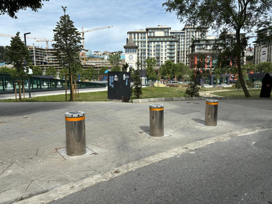
Bollards are exposed to rain, snow, ultraviolet radiation, road salt, exhaust deposits, cleaning chemicals and impact. Stainless steel can offer visual and corrosion benefits, but grade, surface finish, welding treatment and contact with dissimilar metals are important.
Coastal, poolside, chemical or heavily salted environments may require enhanced material selection and more frequent maintenance. Site conditions should be declared to the manufacturer before specification.
 |
|
Understanding IP and IK Ratings
The IP code, defined by IEC 60529, classifies the protection provided by electrical enclosures against solid objects and water ingress. The IK code, defined by IEC 62262, classifies the resistance of electrical enclosures to external mechanical impact.
These ratings normally apply to a defined enclosure or component, not automatically to the complete mechanical installation. An IP rating does not mean that an underground pit can remain flooded, and an IK rating is not a vehicle-impact rating.
Ask the following questions:
• Which component does the IP or IK rating apply to?
• Is a test report available?
• Do cable glands and connectors maintain the stated protection?
• How is water removed from the underground housing?
• How are seals restored after maintenance?
Foundation and Drainage
Most automatic bollards operate below ground level. Rainwater, surface runoff, groundwater and cleaning water can collect in the housing. A layer of aggregate alone is not adequate for every site. Soil permeability, rainfall intensity, groundwater level, drain capacity and backflow risk should be assessed.
Possible solutions include:
• Controlled discharge to permeable ground,
• Connection to a storm-water line with appropriate backflow protection,
• A sump with automatic pump,
• Surface channels and falls that divert water away from the bollard line.
For impact-rated installations, the foundation and anchorage should match the tested configuration. NPSA foundation guidance emphasizes that installation and foundation conditions should meet or exceed those used for the successful test.
Installation Process
1. Site survey: lane width, vehicle turning paths, pedestrian flow, utilities, levels and drainage are recorded.
2. Risk and traffic analysis: vehicle types, peak demand, emergency access and security level are defined.
3. Construction design: bollard axes, spacing, foundations, reinforcement, drainage, conduits, hydraulic lines, control panel and sensors are documented.
4. Utility verification and excavation: existing services are confirmed and excavation is controlled.
5. Foundation, drainage and conduits: water removal and protected cable routes are installed and tested.
6. Positioning and level adjustment: top plates are aligned with finished road level.
7. Concrete and surface finish: reinforcement, concrete, curing and paving are completed without blocking service access.
8. Electrical and control connections: grounding, protection, labeling, sensors and network settings are completed.
9. Commissioning: individual and group operation, safety sensors, manual release, emergency stop and power-failure behavior are tested.
10. Training and handover: operators receive instructions, drawings, serial numbers, test records, warranties and maintenance plans.
Commissioning Checklist
• Smooth and synchronized raising and lowering,
• Correct alignment and finished level,
• Vehicle detection tested with all expected vehicle types,
• Safety sensors prevent unsafe movement,
• Traffic lights operate in the correct sequence,
• Unauthorized access is rejected,
• Manual operation is functional,
• Power-loss and restoration behavior is tested,
• Drainage is tested with controlled water flow,
• Training and handover records are complete.
Maintenance Planning
Maintenance frequency depends on usage, environment and the manufacturer's instructions.
Interval |
Typical Check |
Purpose |
|
Daily / weekly |
Visible damage, debris, warning lights, unusual noise |
Identify early signs of failure |
|
Monthly |
Housing cleaning, drainage, sensors and traffic lights |
Prevent water and dirt accumulation |
|
Every 3-6 months |
Leaks, fluid level, hoses, fittings and fasteners |
Detect wear and loosening |
|
Every 6-12 months |
Control panel, grounding, protection devices, motor and valves |
Verify electrical and drive systems |
|
Annually |
Complete functional and emergency-mode test |
Maintain system-level reliability |
|
Heavy duty / harsh environment |
Shorter manufacturer-defined intervals |
Adapt to high cycles and corrosion exposure |
Maintenance should include cleaning, drainage, fastener checks, sensor adjustment, panel logs and mechanical wear, not only hydraulic fluid. A detailed service record supports trend analysis and spare-parts planning.
Common Problems
Symptom |
Possible Cause |
Initial Check |
|
Slow movement |
Low temperature, fluid level, valve/filter issue or debris |
Temperature, fluid and housing cleanliness |
|
Incomplete raising |
Pressure loss, sensor setting or mechanical obstruction |
Leaks, valves, limits and debris |
|
No response |
Power, fuse, emergency stop, communication or authorization |
Panel status and fault history |
|
Movement while a vehicle is present |
Detection loop or sensor configuration |
Safety test with different vehicles |
|
Water in the housing |
Blocked drain, poor falls, groundwater or pump fault |
Drainage route and pump |
|
Hydraulic leak |
Hose, fitting, seal or impact damage |
Make safe and call trained service personnel |
Integration Options
License plate recognition, RFID, card readers, tag systems, remote controls, mobile applications and central management platforms can be integrated. For remote access, strong passwords, role-based authorization, logs, secure network connections and update procedures should be defined.
Emergency integration must be based on a site-specific risk assessment. Automatically lowering or raising every bollard during an alarm is not universally correct; evacuation, fire-service access and external threats may require different behavior.
What Happens During a Power Failure?
Depending on the design, the system may use a manual valve, hand pump, accumulator, uninterruptible power supply or generator. The required safe state should be defined during design and tested at commissioning.
What Determines the Price?
Total project cost is affected by:
• Type and number of bollards,
• Cylinder dimensions, structural design and finish,
• Central or self-contained drive configuration,
• Operating speed and duty cycle,
• Impact-test requirements,
• Hydraulic and electrical controls,
• Access-control equipment and safety sensors,
• Excavation, concrete, drainage and surface reinstatement,
• Transport, installation, commissioning and training,
• Warranty, service and maintenance scope.
A meaningful comparison separates product, civil works, automation, installation and after-sales support.
White Rose Bollard Solutions
White Rose offers automatic hydraulic, self-contained, manual, fixed and removable bollard product families for different applications. The portfolio includes Tank Compact, Tank PL, Tank PS and Panzer hydraulic families, together with fixed, manual and removable solutions. The White Rose product page also identifies an IWA 14 impact test for the SBM3 fixed model.
The appropriate family should be selected only after evaluating traffic volume, site infrastructure, security level and integration requirements. Technical specifications can change, so dimensions, operating time, duty cycle, enclosure ratings and impact-test claims should be verified against current model-specific data sheets and reports.
Frequently Asked Questions
What does a bollard system do?
It controls vehicle access, restricts unauthorized entry, protects pedestrian zones and can provide a physical security layer appropriate to the project.
Are all bollards impact tested?
No. Impact testing is model specific and must be verified through the complete report and rating code.
How fast does an automatic bollard operate?
Operating time depends on the model. The current technical data sheet should be used, and speed must be evaluated together with safety logic.
Can it work with license plate recognition?
Yes. It can be integrated with license plate recognition, RFID, cards, remote controls and centralized management.
Can a bollard pit remain flooded?
No. An IP rating for a component does not remove the need for proper drainage of the underground housing.
How often is maintenance required?
Intervals depend on usage and environment. Visual checks, cleaning and periodic technical service are normally required.
Can an automatic bollard be used with a boom barrier?
Yes. The boom barrier organizes traffic, while the bollard creates the physical lane restriction. Their sequence should be interlocked.
What documents should be requested?
Current technical data sheets, installation drawings, model-specific test reports, warranty terms, maintenance plan and service scope.
Conclusion
A reliable bollard installation is not only a cylinder, drive mechanism and control panel. It is the combined result of a clear operational requirement, appropriate product selection, engineered foundation and drainage, safety sensors, access-control logic, trained installation and planned maintenance.
Distinguishing routine access control from impact-rated protection, interpreting IP and IK codes correctly and disclosing the site's real environmental conditions are essential procurement steps.
To identify the appropriate White Rose bollard solution, arrange a site survey and review current technical documents with the White Rose project team.


